Understanding CNC File Types
Introduction
Digital fabrication tools like laser cutters, CNC routers, and 3D printers make it possible to produce a physical object from a digital design faster and cheaper then ever before. Designing for digital fabrication, on the other hand, has become more complex. This makes sense because the models need to contain all the information necessary to drive the fabrication process. Different file formats encapsulate information about the model in different ways. File formats are optimized for different purposes and different parts of the workflow process.
Producing digital designs represents a significant investment and protecting this investment is difficult. This article will explain the different types of files you’re likely to encounter and look at some of the considerations you should keep in mind while preparing your designs.
Native Files vs. Exchange Files
Software design tools for producing digital models have become cheaper and more ubiquitous but design itself is inherently difficult. Some software applications provide only a limited set of options to the user and hide the complexity while others provide maximum flexibility and power but come with a steep learning curve. These applications can often read and write many different file formats and new users may be overwhelmed by the dizzying variety of file types and options available.
In general, file formats fall into two broad categories:
Native Files encapsulate information about how the design is constructed within the context of a software application. A design may have parametric features that allow you to change the size or shape of a particular feature. They may have sub-elements that are repeated throughout the final design like a retaining clip that is reused over and over. They may represent an assembly of many smaller components. Native files don’t just contain information about the shape, they contain information about the relationship between elements, and the logic for building up the complex design from simpler elements. They are usually proprietary which means that migrating a design from one software package to another is usually difficult and often impossible.
Exchange Files are intended to facilitate information exchange and interoperability. Exchange means that a design created in one software package can be read, understood, and modified in another. Interoperability implies that the output from one part of the design process can be used as the input for another process or software application. Exchange files don’t contain any of the logic about how a feature was constructed or how it is intended to be used. They only represent the shape of the physical part or parts (Some output file formats can contain multiple solids).
For example, if your design includes many holes intended for a 3mm screw to pass through and you want to change it to accommodate a 4mm screw, modifying the design in the native application file might only require one change and seconds to complete. Modifying the design from the exchange format file might require changing every hole separately and take hours.
Most applications can read and write a variety of exchange formats. For the rest of this article, we’ll mostly concern ourselves with these formats since they are critical to the exchange and interoperability necessary for the manufacturing process.
2D vs 3D
A couple decades ago, all design files were 2D. Whether you were building a house, a bridge, or a mousetrap, design was done with pencil and paper and designs were thus necessarily 2D drawings. The early versions of CAD software replaced the pencil and paper but kept the 2D nature of design.
Real-world objects, however, have depth. Even if the shape is to be cut from a sheet of paper, the paper has thickness. If you are designing your part with a 2D CAD system, you are recreating the third dimension in your mind. Multiple 2D drawings can be used together to help with this mental visualization like when we use a floor plan and elevations to help visualize a house design.
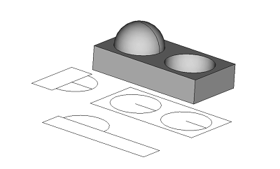
Plan and elevation views help visualize the 3D shape
3D models, unlike their 2D counterparts, represent this depth information explicitly. 3D software not only pans and zooms around the model but also allows the user to rotate it in space and see it from different angles. For more complex models, being able to visualize and modify in three dimensions is very useful. For digital fabrication systems, it’s critical.
Some of the file formats widely used today trace their lineage back to those early 2D CAD applications. The most common being DXF and DWG, both developed by Autodesk. DXF was intended to be an exchange format (the ‘X’ stands for eXchange). Autodesk eventually published the full standard for DXF and it is supported by virtually every cad application available today.
DWG, on the other hand, was the native AutoCAD format and Autodesk has never published the specification. Autodesk became so dominant in the CAD industry that they eventually sold a read/write library so other applications could use the format natively. Reverse engineering efforts also provided some DWG interoperability through open source applications and third party libraries. The formal DWG specification is still not published and has gone through many versions. Compatibility between applications reading and writing DWG isn’t consistent.
Another format that is often used for 2D designs is the Scalable Vector Graphic (SVG). Applications like Inkscape, Adobe Illustrator, or CorelDraw are intended for working with SVG. SVG wasn’t intended as an engineering format. It was developed first as a web technology. It’s a vector based graphic format which means the shapes are not defined by their pixels but are entirely represented mathematically. This means they can be scaled up or down in size without loss of resolution and it’s easy to compute a tool path from the lines.
SVG files are an especially common input format when setting up a part to be cut on a laser cutter. Elements in an SVG file can be grouped together or assigned a color. Using these groups and colors, a designer can indicate which elements should, for example, be cut with the laser on high power and which should be engraved with the laser at lower power. Unfortunately, there’s no consensus about how colors and groups should be interpreted so reworking SVG files for laser cutting is common.
SVG and DXF are exclusively 2D standards while DWG has been extended to encode 3D data as well.
Solid Models vs Meshes (Tessellation)
Solid models are analogous to the SVG format mentioned above. They represent their shapes through pure mathematics. Curved surfaces are truly curved at any resolution. Solid model formats can be complex but are better suited to engineering operations. They can represent more aspects of the model than just the exterior surface so they can be used in more kinds of engineering operations. The two most common formats for solid model exchange are STP (Standard for the Exchange of Product model data) and the older IGES (Initial Graphics Exchange Specification). Both are supported by most 3D applications today but STP has largely supplanted IGES which is declining in popularity.
When 3D printing was developed as an additive manufacturing technology, the stereo lithography (STL) format was also created. Instead of representing the part surfaces with pure mathematics, STL approximates the outer surface of the shape with a series of triangular faces. If a very close approximation is desired, a large number of faces can be employed but the file will be correspondingly large. If a smaller file is desired or high precision is not needed, a courser approximation or tessellation will suffice. The STL format is lightweight, easy to process computationally, and widely supported. Formats like STL which only represent the outer surfaces of the part with flat faces are called mesh formats.
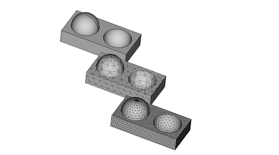
A mesh can approximate the original shape at different levels of accuracy
Another mesh format has been introduced specifically for the additive manufacturing (3D printing) world: Additive Manufacturing File Format (AMF). AMF describes the geometry of the part just as an STL does but is also capable of describing color, materials, and other attributes. These additional attributes can help modern 3D printers automatically configure themselves to produce better finished parts.
Computationally, it’s very simple for a computer to convert a solid model to a mesh model. Most software that can work with solid models will have this capability. However, going the other way, from a mesh to a solid, is very difficult. Trying to derive the curved surface from the approximation is complicated and error prone. Some software packages include tools to do this but the results are never ideal and mistakes are common.
G-code (RS-274)
If you’ve used a CNC machine like a router or a 3D printer, you’ve probably seen G-code. G-code is the common name for a widely used programming language for controlling automated machine tools. G-code isn’t really a representation of the part or model being made. Rather, it contains all the instructions necessary to prepare the machine, load the tool, and move the tool in space. It’s the set of instructions to the machine how to make that part. G-code files are written as normal text files. They can be modified with any text editor.
Just as most software packages have a native file format which is specific to it, G-code is specific to the machine that runs it. Different variants of G-code exist for different machine controllers and code written for one machine controller likely won’t work on another.
G-code also contains the instruction about how fast to move a tool (feed rate) and how fast the tool moves past the material (surface speed) and these numbers depend heavily on what kind of material is being cut. Thus g-code written to cut a part from aluminum won’t work to cut the same part from steel.
G-code is an old language. The first versions were developed in the 1950s which computer memory was limited and programs were written by hand by programmers who specialized in it. Today, almost no one writes g-code directly. Instead, Computer Aided Machining (CAM) software produces G-code automatically and optimizes, or post processes, it for the specific machine on which it will run.
The G-code specification includes commands that describe curved motion. These commands, like G2 and G3, for example, specifying the start point, end, point, and center of the arc. This helps keep g-code programs very small and efficient. But not all machine controllers are able to use arc commands. Many machine controllers, especially those used by hobbyists can not interpret them at all. When a curve is needed, the CAM software uses a process called discretization to break the arc into many discrete small straight lines that approximate the curve. If a very smooth curve is desired, the individual straight lines will be incredibly small and the resulting file will be quite large.
File Formats Compared
| Extension | Format | Purpose | 2D vs 3D | Proprietary vs Open |
|---|---|---|---|---|
| DXF | Drawing Exchange Format | Exchange | 2D | Open |
| DWG | AutoCAD Drawing | Design | 2D/3D | Proprietary |
| SVG | Scalable Vector Graphic | Design/Exchange | 2D | Open |
| STL | Stereo Lithography | Exchange/Interop | 3D | Open |
| AMF | Additive Manufacturing File Format | Design/Exchange | 3D | Open |
| STP, STEP | Standard for exchange of Product Model Data | Exchange | 3D | Open |
| IGES, IGS | Initial Graphics Exchange Specification | Exchange | 3D | Open |
| NC, NGC, TAP, CNC, GCODE | G-code | Execution | N/A | Open (many variants) |
| AI | Adobe Illustrator | Design | 2D | Proprietary |
| BREP, BRP | Boundary Representation | Design/Exchange | 3D | Open |
Final Thoughts
What can you do to protect your design investment?
Consider Design Software Carefully
It’s tempting to choose a design software with the simplest learning curve, most powerful features, or most beautiful interface. For preserving the long-term utility of your designs, however, you should carefully evaluate whether the software can read and write the most common exchange formats reliably. Software applications need native formats to support unique features and advanced workflows. Companies will sometimes use their native formats to lock in users and lock out competition. Make sure your application provides robust methods to migrate your data to other systems. If you need to change design applications in the future, you may need to do extensive rework on your files. This work will be far easier if you are starting from a solid model format like STP rather than a mesh approximation of the part like STL.
When sharing your designs or collaborating with others, share the format that you can both read which has the highest information density possible. If you are both using the same software, share the native application project file. If you use different software, opt for solid models and exchange formats like STP and DXF over tessellated meshes and graphics formats like STL and SVG.
If you are going to have one of your parts cut by a professional CNC shop, job shop, or fabricator, they will almost certainly not use g-code that you generated from your CAM software. Such g-code will not be optimized for their machine and they will not trust it. Most shops will prefer to work from a solid model or DXF file and many will even insist on recreating the design in their own design software from paper drawings (and probably charging you a setup fee for the effort)!
If you run your own CNC, keep your old g-code files along with your native project files and backed up exchange formats. The g-code encapsulates information and decision from the CAM setup that is not stored elsewhere in the design. If you need to re-run the job in the future, the g-code can be a lifesaver.
Think carefully before committing to a cloud-based design service. If the service becomes unavailable for any reason, will your designs be protected? Can you migrate away from the service in the future without losing your designs or being forced to recreate them from a low quality export?
Consider CAM Software Carefully
There’s often a close relationship between the tools used to design a part and those used to generate the CNC tool path. If you are generating your own g-code, you might find it beneficial to choose a design application with native CAM. Tools like this can automatically update the CAM configuration and g-code output if the part design changes.
If you run your own CNC, keep your old g-code files along with your native project files and backed up exchange formats. The g-code encapsulates information and decision from the CAM setup that is not stored elsewhere in the design. If you need to re-run the job in the future, the g-code can be a lifesaver.
If you will have your parts cut by a professional CNC operator, job shop, or fabricator, they will almost certainly not use g-code that you generated from your CAM software. Such g-code will not be optimized for their machine and they will not trust it. Most shops will prefer to work from a solid model or DXF file and many will even insist on recreating the design in their own design software from paper drawings (and probably charging you a setup fee for the effort)!
Make Backups Wisely
If you only back up your project files - the native application file, you may find compatibility problems in the future. Software applications change faster than file standards. In the future, your software may support a feature in a different way or the software may not be affordable or even available. When you back up your project files, take a moment to export the parts in one of the open format exchange standards as well. In the event that your software can’t read the project file, it will almost certainly be able to import the exchange format.