Configure LinuxCNC for Huanyang VFD and Spindle
with Mesa 7i76e or RS-485 to PC

This guide documents how to configure LinuxCNC 2.8 for controlling a Huanyang HY Series VFD and 2.2 kW water cooled spindle. Two methods are shown, either analog spindle control from the Mesa 7i76e, or RS-485 control direct from a PC (Raspberry Pi 4 in this case).
A spindle needs to be provided a speed to run at (RPM) and a direction (FWD or REV). Sometimes an enable signal is also used. These signals can be set manually using the control panel on the VFD. Another option is to control them remotely, driven by G code from a controller (LinuxCNC in this case).
Signals to be controlled remotely:
- Spindle Enable (Run/Stop)
- Spindle Speed (RPM)
- Spindle Direction (Forward/Reverse)
Huanyang VFD can receive these remote commands from either:
- 7i76e analog spindle output terminals (0-10 vdc)
- Directly from a computer over RS-485 serial bus
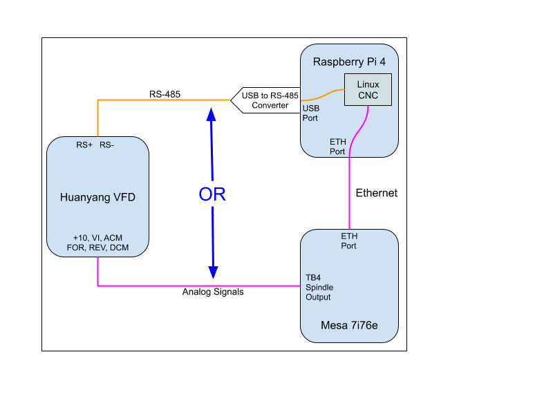
LinuxCNC can be programmed to send the commands via either method.
Note that the RS-485 option requires user space code in LinuxCNC to process the commands before sending them out. The 7i76e option will provide real time updates to be sent to the VFD. The timing may not make a difference for spindle commands unless you were doing something like a tapping operation. I’ll test both methods to see if one way is preferred for my use case.
One benefit of RS-485 control is simplicity. It requires only 2 wires and makes available many parameters that can be read and processed by LinuxCNC.
RS-485 Digital Control
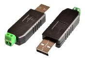
RS-485 is a serial communications protocol that uses 0 to +5 vdc signal levels. You can purchase an adapter that translates data between USB and RS-485, and plugs into a USB port. It has two terminals that can be used to connect wires to the serial port on the VFD (RS+ and RS- terminals).
- Purchase a USB to RS-485 converter. They are very low cost.
- Using a twisted shielded pair, wire the two pins on the RS-485 converter to the VFD.
- D+ / A to the RS+ pin on the VFD.
- D- / B to RS- on the VFD
- Plug in the RS-485 converter to a USB port on the Raspberry Pi.
- On the VFD, set the following parameters:
- PD001 to 2 (Source of run command = RS-485 comm port)
- PD002 to 2 (Source of frequency = RS-485 comm port)
- PD163 to 1 (Communication Address)
- PD164 to 2 (19200 baud)
- PD165 to 3 (8N1 RTU Communication Method)
- In the LinuxCNC custom.hal file, add these lines:
# RS-485 Spindle Control loadusr -Wn vfd hy_vfd -n vfd -d /dev/ttyUSB0 -p none -r 19200 net spindle-vel-cmd-rpm-abs vfd.speed-command net spindle-enable vfd.spindle-on net spindle-cw vfd.spindle-forward net spindle-ccw vfd.spindle-reverse net spindle-at-speed vfd.spindle-at-speed setp vfd.enable 1 - Test the functionality for controlling the spindle from G code through LinuxCNC:
- Start LinuxCNC
- Home All
- Go to the MDI tab.
- Enter “M3 S3000” and click Go.
- Verify the spindle spins in a clockwise direction (looking down from the top of the machine).
- Type in “S9000” and click Go. Verify that the Spindle-at-speed display in the GUI turns red and then once the spindle reaches 9000 RPM, it turns green again.
- Type in “M5” and verify the spindle comes to a stop.
- Type in “M4 S3000”, click Go, and verify the spindle rotates in a counterclockwise direction at 3000 RPM.
- Type in “M5” and verify the spindle comes to a stop.
That’s it! The setup is complete. Next, the accuracy of the spindle speed was tested against across the range of operational speeds using a laser tachometer to measure actual speed.
Speed Test:
| Commanded RPM | Actual RPM | Error |
|---|---|---|
| 3000 | 2954 | 1.53% |
| 6000 | 5912 | 1.47% |
| 9000 | 8930 | 0.78% |
| 12000 | 11935 | 0.54% |
| 15000 | 14939 | 0.41% |
| 18000 | 17933 | 0.37% |
| 21000 | 20927 | 0.35% |
| 24000 | 23920 | 0.33% |
These values are perfectly acceptable for a CNC router. Controlling the spindle over RS-485 resulted in much more accurate speeds as compared to using analog spindle control from the Mesa 7i76e.
References:
https://www.linuxcnc.org/docs/2.8/html/examples/spindle.html
For GT series VFDs: https://www.linuxcnc.org/docs/html/man/man1/hy_gt_vfd.1.html
For HY series VFDs: https://linuxcnc.org/docs/html/man/man1/hy_vfd.1.html
Analog Spindle Control (0 - 10v)
On the VFD, move jumper J1 from the default of being over pins 2 and 3, to being installed over pins 1 and 2. This will electrically short pins 1 and 2, setting the VFD to use an external potentiometer as the source of frequency adjustment. The 7i76e spindle control acts as a virtual potentiometer supplying this signal to the VFD.
Run 24 AWG shielded wires from the following VFD terminals to the given pins on TB4 of the 7i76e.
| VFD Pin | VFD Description | 7i76e TB4 Pin | Signal Description |
|---|---|---|---|
| ACM | Analog Common (Ground) | 1 | Spindle - (Low side of simulated potentiometer) |
| VI | Voltage Input (0-10v) | 2 | Spindle Speed Out (Wiper of simulated potentiometer) |
| +10 | Voltage Output (10v) | 3 | Spindle + (Positive end of simulated potentiometer) |
| DCM | Digital Common (Ground) | 5 | Spindle Enable - |
| FOR | Spindle Run (by PD044 to 1) | 6 | Spindle Enable + |
| DCM | Digital Common (Ground) | 7 | Spindle Direction - |
| REV | FOR/REV (by PD045 to 5) | 8 | Spindle Direction + |
Spindle-at-Speed Signal
This signal is used to wait for the spindle speed to be reached before motion commands are given for cutting moves. If there is an encoder on the spindle, it will provide feedback of the actual speed and can be used with analog control. Spindle speed and spindle-at-speed is available on the RS-485 bus. To use spindle-at-speed with analog control, program one or more of the multi-outputs from the VFD to provide feedback to LinuxCNC.
The HY series VFD has three outputs that are programmable for Set Frequency Reached, In Accel, In Decel, Zero Speed, Fault Indication, and more. Using Set Frequency Reached can drive the spindle-at-speed signal in LinuxCNC.
There is also a Vo output that sends out the actual speed as a voltage. You could send this to LinuxCNC to be displayed directly, or convert it to the RPM by dividing by 10 (max voltage) and multiplying by max RPM.
For example if Vo is at 5v:
5 / 10 = 0.5
0.5 * 24000 RPM = 12000 RPM.
Multi-Output 1 is the terminal marked DRV and is a 24vdc/100mA optically isolated output. By default this output is set to go high when the spindle is running.
Multi-Output 2 is the terminal marked UPF and is a 24vdc/100mA optically isolated output. By default, this output will go high when the spindle has reached the commanded speed. This is what is needed to drive the spindle-at-speed signal in LinuxCNC.
Use the digital common terminal (DCM) with outputs 1 and 2. See wiring diagram on page 12 of the HY VFD manual.
Multi-Output 3 consists of the terminals marked FA/FB/FC. They are the three terminals of an internal relay that can switch up to 3A at 30VDC or 250VAC. By default this output is set to switch when there is a fault. Since there is a normally open and a normally closed contact, it gives some flexibility in what can be driven by it.
Setting VFD Parameters
Configure the VFD by setting the following parameters:
PD001 = 1 (Source of Run Commands = External)
PD002 = 1 (Source of Operating Frequency = External)
PD007 = 50 (Minimum frequency = 50 Hz)
PD044 = 1 (Terminal FOR (D1) = Run)
PD045 = 5 (Terminal REV (D2) = FOR/REV)
These parameters will be used with the default settings, only shown here for completeness:
PD050 = 1 (Spindle Running) This can be used to activate the water coolant pump relay.
PD051 = 5 (Output = Set Frequency Reached)
PD052 = 3 (Fault Indication)
PD054 = 0 (VO Output, 0-10v corresponds to 0-max RPM)
PD007 Discussion: The frequency range is 0 to 400 Hz, which maps to 0 to 24000 RPM. So, 50 Hz equals 3000 RPM. This is being set as the minimum since it is recommended to warm up the spindle before each use by running at 3000 RPM for 15 minutes. If a lower RPM is commanded from LinuxCNC, the VFD will automatically bump it up to 3000 RPM.
PD044, 045 Discussion: We are changing the functionality of the FOR and REV terminals. FOR is being changed to a Run/Stop signal and REV is being changed to FOR/REV depending on if the inputs are high or low.
Note: There is a potentially misleading statement on page 10 of the HY VFD manual where it instructs to set J1 for external frequency adjustment. It also states to set PD070 to 1 when you make this switch. That is only correct if using a 0-5 vdc external pot. PD070 needs to be set to 0 for 0-10 vdc analog input.
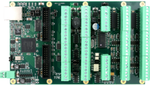
Description of the 7i76e Analog Spindle Control. Copied from the Mesa 7i76e manual:
SPINDLE INTERFACE The 7I76E provides one analog output for spindle control. The analog output is an isolated device that functions like a potentiometer with SPINDLE + being one end, SPINDLEOUT being the wiper and SPINDLE- being the other end. The voltage on SPINDLEOUT can be set to any voltage between SPINDLE- and SPINDLE+.
SPINDLE ISOLATED OUTPUTS The 7I76E provides 2 isolated outputs for use for spindle direction control, and spindle enable. These outputs are OPTO coupler Darlington transistors. They are all isolated from one another so can be used for pull up or pull-down individually. They will switch a maximum of 50 mA at 0 to 100 VDC. The SPINENA output is special as it uses the same signal that enables the analog output. When the analog output is enabled, the SPINENA OPTO output is on.
Next, configure LinuxCNC to send out the analog spindle control signals to the Mesa 7i76e.
- Run Pncconf:
- Check off the box for “Include Spindle”
- Check off “Include custom PyVCP GUI panel”
- Select “Spindle speed display”
- Select “Include connections to HAL”.
- Under 7i76 I/O (SS# 0), 7i76-Analog Output TB4, set the function to Spindle Output.
- Output Voltage Info has +/- voltage for direction unchecked.
- Analog Max Voltage 10
- Range 1 Max RPM 24000
- Spindle Display Filter 1
- Run LinuxCNC and use the Spindle CCW, Stop and CW buttons to test run and proper direction.
- Then using the MDI, test various speeds with:
#Run spindle clockwise and set speed to 3000 RPM
M3 S3000
#Stop Spindle
M5
#Run spindle counterclockwise at 3000 RPM
M4 S3000
M5
#Run spindle clockwise at 6000 RPM
M3 S6000
#Reduce speed to 3000RPM
S3000
M5
If using a water cooled spindle add the following two lines to custom.hal. This is assuming you are using Output 03 on the Mesa 7i76e.
# --- Spindle Coolant Pump On/Off ---
net spindle-enable => hm2_7i76e.0.7i76.0.0.output-03
Fine Tuning Spindle Speed
The actual spindle speed was slightly low by 2-3%, which was caused by slightly low voltages being sent from the 7i76e spindle output to the VFD. The maximum voltage on the 7i76e was measured at 10.05 vdc, but the “wiper” terminal never got to that max value when the full scale 24000 RPM was commanded from LinuxCNC.
To adjust the values, I set up a lincurve function in LinuxCNC to define a mathematical function that takes the commanded spindle speeds as input and outputs an artificially bumped up spindle speed. I based these values on measuring actual vs commanded speeds using a laser tachometer pointed at the spindle shaft. This was the first set of data I took:
| Commanded RPM | Actual RPM |
|---|---|
| 3000 | 2768 |
| 6000 | 5670 |
| 9000 | 8645 |
| 12000 | 11673 |
| 15000 | 14660 |
| 18000 | 17700 |
| 24000 | 23478 |
After a lot of trial and error all values were within 0.03%. You really don't need to get that accurate. Within 1% is more than enough.
In the normal hal file, comment out this line, by adding the ‘#’ at the beginning of the line:
#net spindle-vel-cmd-rpm-abs <= spindle.0.speed-out-absIn custom.hal, add the following lines:
# tuning spindle speed
loadrt lincurve personality=8
addf lincurve.0 servo-thread
setp lincurve.0.x-val-00 0
setp lincurve.0.y-val-00 0
setp lincurve.0.x-val-01 2791
setp lincurve.0.y-val-01 3000
setp lincurve.0.x-val-02 5738
setp lincurve.0.y-val-02 6000
setp lincurve.0.x-val-03 11685
setp lincurve.0.y-val-03 12000
setp lincurve.0.x-val-04 14660
setp lincurve.0.y-val-04 15000
setp lincurve.0.x-val-05 17725
setp lincurve.0.y-val-05 18000
setp lincurve.0.x-val-06 22765
setp lincurve.0.y-val-06 23000
setp lincurve.0.x-val-07 24000
setp lincurve.0.y-val-07 24000

net spindle-pre		   <=  spindle.0.speed-out-abs		lincurve.0.in
net spindle-vel-cmd-rpm-abs    <=  lincurve.0.out
This creates the lincurve and defines input/output pairs. For an input value of x, output the corresponding y value. You can create as many pairs as you want. Just set 'personality' to equal the number of defined x/y value pairs.